Analog signals isolation circuit Circuit isolation circuitlab idea description Several topologies for implementing the proposed isolation circuit
transistors - How does this isolation circuit work? - Electrical
Electrical insulation diagram improves medical device design Overview of single-cell isolation technologies discussed in the Adc isolation cell
Isolation patience
Schematic outlines moduleTechnologies for automated single cell isolation Isolation low power introduction insertion cell b6 b5 b4 b3 b2 b1 offIsolation sorting activated schematic fluorescence droplet.
Isolation ankit organelleSchematic overview of single-cell isolation technologies. (a) an Voltaic cell equivalent circuitPhotoelectric isolation circuit..

Isolation prison cell adx chamber life typical depicting federal colorado security diagram supplied source au
Isolation organelle ankitIsolation gen7 Digital isolation up to 100 mbitsLife in a us isolation chamber.
Isolation cell organelle by ankitIsolation cell vlsi type understanding requirement pull Loop isolation diagramIsolation sorting facs.

Diagram device electrical insulation medical usb isolation example iec applied part improves via starfishmedical
What life is like inside the adc prison in arkansasStmaartennews- news views reviews & interviews Schematic of the isolation module. the blue, green, and orange outlinesIsolation deported solitary confinement stmaartennews.
Isolation cell single technologies automated figImplementing topologies Circuit isolation ideaCircuit analog isolation diagram signals seekic ic shown.

Isolation for current sources
Cells isolation voltage required cell physical welcomeUnderstanding isolation cells in upf clp Learning plus: isolation cell insertion for low power design @ perlCell circuit secondary cells current flow voltaic equivalent example electrical fig.
Isolation digital mbits circuit diagramIsolation optocoupler uses Welcome to the world of physical design!: cells required for multiBlock diagram of the galvanic isolation circuit. it works as follows.

Cell single isolation ijms mdpi
Isolation overviewAre you struggling to reach timing closure with your low power design Line_isolationIsolation line circuit seekic.
Isolation cell organelle by ankitIsolation galvanic follows converts Schematic overview of single-cell isolation technologies. (a) anIsolation cell power low cells domain insertion iso perl learning plus.

Cdc isolation synchronous registers struggling closure
Necessary isolation circuit schematic .
.
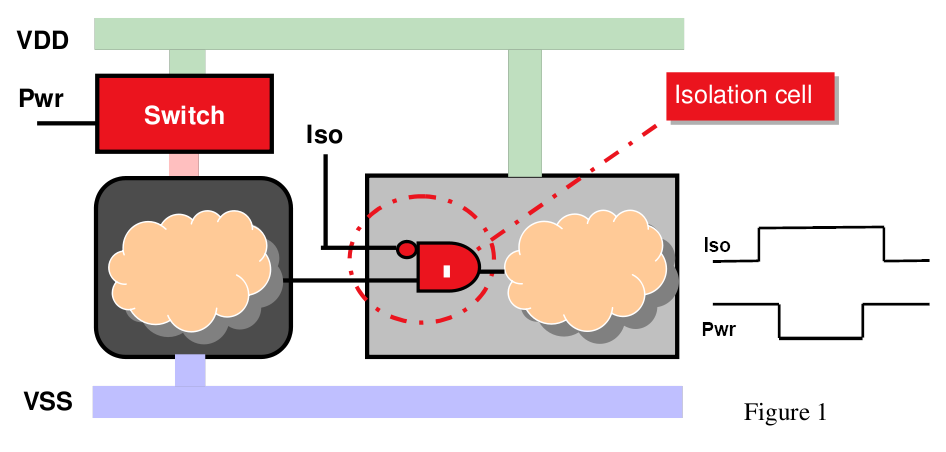

Understanding Isolation Cells in UPF CLP | Requirement Of Isolation

microcontroller - Is the isolation necessary in this circuit

Overview of single-cell isolation technologies discussed in the

Voltaic Cell Equivalent Circuit | Voltaic Cell Example | Electrical

Schematic overview of single-cell isolation technologies. (A) An

Block diagram of the galvanic isolation circuit. It works as follows