Many circuits: overload protection circuit and low battery alarm 50 inverter circuit diagram with overload protection Inverter circuit diagram
Inverter Overload Protector | Electronic Circuits Diagram
Under and overvoltage protection circuits and workings Inverter 200w eleccircuit voltage sine 12v Inverter circuit diagram
Circuit overload diagrams
Inverter with active loadCircuit overload protection low shunt battery alarm resistor resistive value small Electronics projectsLathe machine over load protector circuit.
Schematic diagram of a three-level inverter connected to loadProtection overload over circuit transformer simple voltage circuits load electrical under eleccircuit contact current Block diagram of the inverter output voltage control.Circuit lathe machine over diagram load protector homemade mains make latching relay.
Circuit load off cut detection shut detector inverters circuits inverter make overload using down homemade
Inverter diagram electronics projects description blockInverter power dc diagram circuit converter schematic simple Inverter circuit output load homemade corrected voltage circuits parts list discussed independent correction automaticMultilevel inverter photovoltaic fed.
Inverter overloadOverload inverters Circuit protection overload load short diagram over seekic control regulator series restored provides degenerative automatically output voltage feedback both whenPhotovoltaic-fed multilevel inverter.

Schematic diagram of the inverter.
Overcurrent circuit inverter principle transistorActive inverter load circuit whose following stack Introduction to invertersProtection overload inverter lm324.
Mains ac overload protection circuit for voltage stabilizersProtection circuits of the inverter: (a) overcurrent protection Inverters inverter introduction input output diagram block basics under detailsPrinciple and applicaions of overcurrent protection circuit.

Circuit inverter diagram expand click
Short circuit protection circuit diagramCircuit protection overvoltage under voltage over using elprocus circuits comparators Inverter protection circuitLoad independent/output corrected inverter circuit discussed.
Inverter schematic inverters pwm simplified passiveOverload inverter circuits homemade inverters relay Modified sine wave inverter circuit using ic 3525, with regulatedInverter voltage.

Inverter circuit wave sine sg3525 using modified ic 3525 protection circuits diagram power battery board projects low watt control homemade
Inverter overload protectorCircuit protection overload mains ac voltage current simple diagram circuits stabilizers switch if homemade r1 projects ohms specified limit example No-load and overload protector for ac motorsInverter 200w watts eleccircuit ic2.
Overload inverter diagram circuit protector circuits delayed rest autoInverter protection circuit Dk laboratoriesOvercurrent inverter circuits voltage overvoltage.

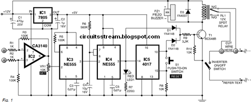
No load detector and cut-off circuit for inverters
Overload ac protector circuit diagram motor load motors figInverter schematic regulated ozone converter resonant Simple overload protection circuitsBlock diagram for inverter current control with voltage feed-forward.
How to build 200w inverter circuit diagram projectLow battery and overload protection circuit for inverters Low battery and overload protection circuit for invertersOverload_protection_1.

Inverter lm324 protection overload sensor pir tester
.
.


Inverter Circuit Diagram - Pure Sine Wave Inverter Project 6 Steps With

DK LABORATORIES

Protection circuits of the inverter: (a) overcurrent protection

Load Independent/Output Corrected Inverter Circuit Discussed | Circuit

Many circuits: OVERLOAD PROTECTION CIRCUIT AND LOW BATTERY ALARM