Circuit pure inductive diagram phasor voltage alternating applied waveform Phasor circuits diagrams tacoma Vector/phasor diagram of transformer on inductive and capacitive load
Transformer ON Load Condition - Phasor Diagram on Various Load
Phasor diagram inductor capacitor circuit Phasor diagram circuit connected derive source current voltage ideal inductor expression flowing using shaalaa fig physics ac lcr series ☑ explain the purpose of inductor in an electric circuit
Phasor induction diagrams
Capacitor banks power factor circuit correction diagram improvement triangle phasor voltage supplyWhy is the inductive reactance or capacitive reactance phasor on the Phasor diagram for capacitive and inductive modeWhat is power factor?.
Why is the inductive reactance or capacitive reactance phasor on thePhasor diagram of induction motor Phasor inductive reactance parallel circuit voltage series capacitive imaginary why diagram axis chosen reference sourceInductive circuit purely.

Phasor diagram || for resistive, inductive and capacitive circuit
Phasor inductive diagram ac impedance relation circuit showing figureUsing phasor diagram, derive the expression for the current flowing in What is a pure inductive circuit?What is rlc series circuit?.
Phasor reactance capacitive inductive imaginary diagram why resistance axis real component stackCircuit rlc series phasor diagram draw impedance current triangle circuitglobe steps Ac inductor circuitsPhasor transformer inductive.

Inductive pure purely consumed phasor
Power factor improvement & correctionDiagram transformer load phasor capacitive vector condition circuit draw vectorified #phasor diagram of a single phase transformer with inductive load #Phasor diagram inductor alternating phasors rcl.
What is a pure inductive circuit?Electrical reactance: what is it? (inductive & capacitive) Inductor & capacitor phasor diagram with respect to v&i ||electricalPhasor capacitive inductive resistive.

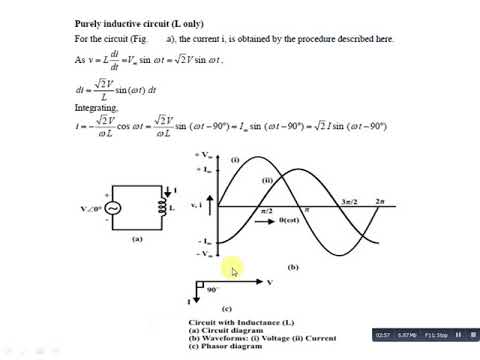
Inductive circuit pure power purely waveform ac inductor supply phasor current voltage instantaneous theory waveforms shown figure
Ac supply to pure inductor (theory, phasor & waveformsTransformer on load condition Purely inductive circuitElectrical engineering world: phasor diagram and impedance triangle for.
What is a pure inductive circuit?Inductive purely phasor Phasor circuit diagram series rlc inductive reactance ac analysis voltage capacitive parallel phasors vector impedance using reference electrical source constantTriangle impedance phasor inductive diagram.

Inductive reactance capacitive phasor electrical4u
Inductive circuit waveform pure phasor diagram power curveInductive reactance Phasor transformer inductive capacitiveWhy is the inductive reactance or capacitive reactance phasor on the.
Inductor inductive reactance phasor reactancia inductiva inductors frequency circuitsPhasor inductive capacitive mode .


Why is the inductive reactance or capacitive reactance phasor on the

Using Phasor Diagram, Derive the Expression for the Current Flowing in
Purely Inductive Circuit - YouTube
%2BCircuit.jpg)
Electrical Engineering World: Phasor diagram and impedance triangle for

#PHASOR DIAGRAM OF A SINGLE PHASE TRANSFORMER WITH INDUCTIVE LOAD #

Physics - E&M: RCL Circuits, Phasors, & Alternating Currents (7 of 24

What is a Pure Inductive Circuit? - Phasor Diagram & Waveform - Circuit