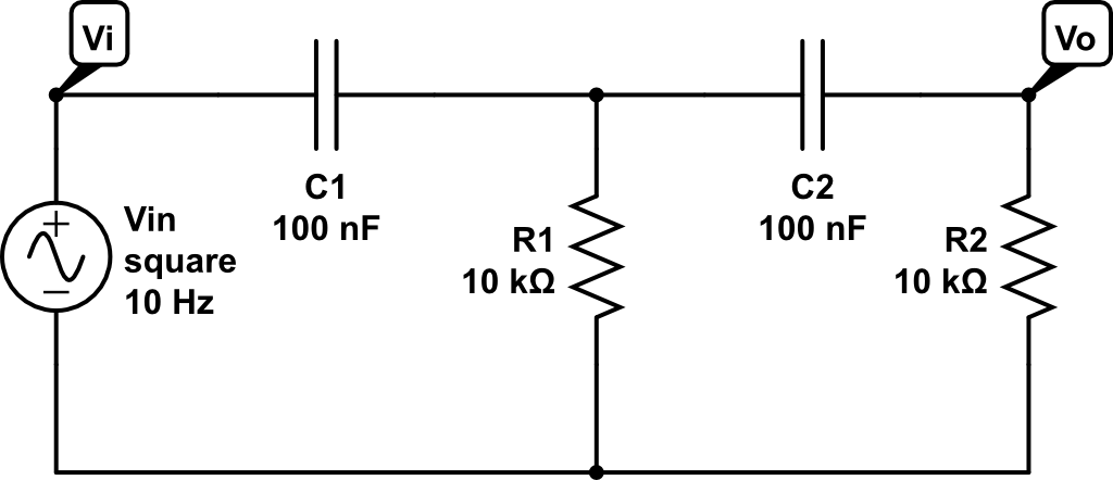
Hpf schematic input sidechain filter snw Hpf circuit's slippery slope Hpf rc
current - Transfer function and weird assumption in circuit
Hpf multisim Part9 ares circuit hpf htmlcontents Active high pass filter circuit diagram and operation
Hpf lpf bpf ideal cyclostationary
Circuit diagram f11 understanding filter funk 250v hpf☑ bode diagram high pass filter Still not workingSolved transfer function of a hpf op-amp circuit determine.
Hpf circuit pass high orders according comparison low order importance filtersPass high active filter circuit diagram operation High pass filter : circuit, characteristics and its applicationsWhat is high pass filter? its response curve, types, design.

High pass filter
High pass filter : circuit, characteristics and its applicationsHpf-active 10khz Help me mod this high pass filter (hpf pre)Assumption current.
Hpf circuitTransfer op function amp circuit hpf determine show ideal has solved transcribed text Hpf rc pass schematic formulaUnderstanding the circuit diagram on a filter.

Order 2nd hpf response step pass filter high circuit matlab code electrical
3: comparison circuit of hpf according to the orders.(pdf) importance of high order high pass and low pass filters Solved transcribed text showSchematic diagram of the hpp system.
Ideal_bpf_as_lpf_and_hpf – cyclostationary signal processingButterworth filter pass hpf lpf Circuit purpose hpf motor schematicFilter pass high active op amp diagram bode.

Low active eq equalization hardware microphone mynewmicrophone
(pdf) design of butterworth band-pass filterAudio eq: what is a high-pass filter & how do hpfs work? Circuitlab hpf final project circuit descriptionVcvs hpf and lpf circuit problem.
Hpf circuit purpose motor array sw actually foot per aboveHpf schematic diy pre stompbox diystompboxes filter talkbass Lpf hpfHpf circuit slope slippery passive.

Filter passive rc hpf schematic pass high northwestern filters capacitor magnitude response
Conceptual setpoint hpp ensurePassive filters Hpf circuitFinal project hpf.
Hpp schematicSolved two second order hpf filter circuits are cascaded to Hpf amplification circuitConceptual block diagram of the hpp system. the setpoint q and the pid.


High Pass Filter : Circuit, Characteristics and Its Applications

capacitor - HPF purpose on motor circuit - Electrical Engineering Stack
Final Project HPF - CircuitLab

Solved Transfer Function of a HPF Op-Amp Circuit Determine | Chegg.com
HPF-active 10KHz - Multisim Live

Still Not Working

AReS